
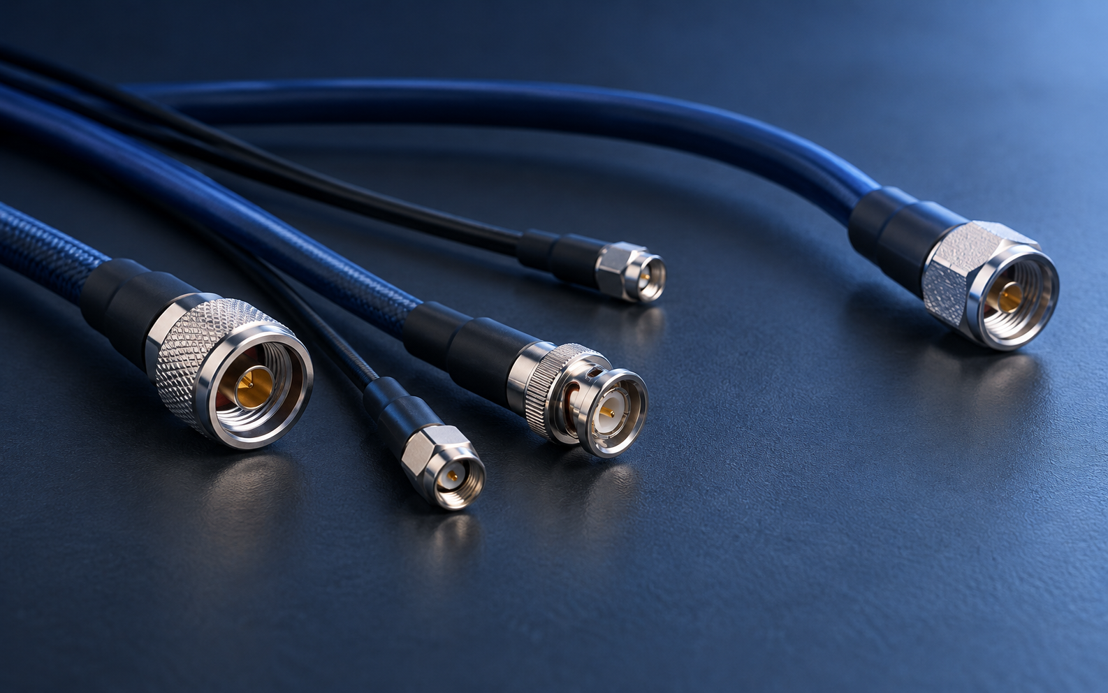
An RF cable assembly is more than a cable cut to length. Cable construction, connector interface and installation conditions all influence the signal that reaches the next stage. The following six questions turn a vague request into a specification that can be quoted and checked.
1. What frequency range must it cover?
State the full operating band and any expected future range. Cable attenuation generally rises with frequency, while connector and assembly performance must also be suitable at the highest operating frequency. A lower-frequency test result should not be treated as proof of performance across a wider band.
2. What loss budget is available?
Define the maximum insertion loss at relevant frequencies and at the final assembly length. Include connector transitions in the budget. In a receive path, extra loss ahead of a low-noise amplifier can degrade system sensitivity; in a transmit path, it reduces delivered power and adds heat. A short, low-loss route may therefore be more valuable than selecting cable by diameter alone.
3. Which connector interfaces are required?
Identify both ends separately: interface family, gender, orientation and mounting arrangement. Verify mating compatibility with the equipment rather than relying on a connector's appearance. Connector choices should also consider frequency rating, mating cycles and the space available for torque tools.
4. How will the assembly be installed?
Provide the finished length and routing sketch if possible. Note minimum bend radius, repeated flexing, vibration, outdoor exposure and temperature range. A cable that performs well in a straight laboratory setup may not suit a tight or frequently moved installation. Include strain relief where the cable meets a connector or bulkhead.
5. Which electrical checks matter?
Common acceptance checks include insertion loss and return loss or VSWR across the operating band. Depending on the use case, phase stability, shielding or power-handling requirements may also matter. Define the reference planes, cable condition during testing and pass criteria so supplier and buyer evaluate the same thing.
6. What documentation is needed?
For repeat orders, identify part numbering, connector drawings, length tolerance, labeling and test-report expectations. These small details make replacement assemblies more consistent and simplify incoming inspection.
Send RFsatellite your band, assembly length, end connectors and installation environment for a focused discussion. Explore our RF cable assembly overview or contact the team.