
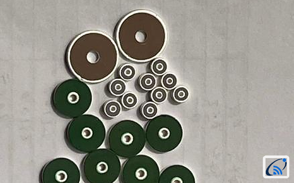
In a shielded RF cavity, every capacitor that crosses a bulkhead is both a DC path and an EMI risk. Conventional chip and leaded capacitors were never designed for this job: their leads and long solder pads add parasitic inductance exactly where the filter needs to be invisible. Feed-through disc capacitors solve the problem structurally — the center through-hole passes the bulkhead itself, and the ceramic body becomes the feed-through.
The ESL problem with leads and long pads
A leaded capacitor's self-resonant frequency drops as lead inductance rises, which weakens RF filtering and DC blocking in exactly the bands that matter. Batch-to-batch lead and pad variations also spread ESL values, so each amplifier ends up needing its own RF calibration. That is labor cost hiding in the BOM.
Direct bulkhead soldering removes the extra parts
Feed-through disc capacitors use co-fired precious-metal (Ag/Pd) electrodes that solder directly onto the shielding metal wall — no brackets, no extended leads, no adapters. The integrated hollow disc keeps current paths short and symmetric for ultra-low ESL, and the center through-hole joins the amplifier chamber and control circuit with EMI isolation built in. That saves cavity space and assembly cost at the same time.
Two dielectrics, two jobs
One dielectric rarely serves both precision RF and power decoupling. The NPO version offers 0±30 ppm/°C temperature stability for precision RF references, while X7R covers 10 pF to 12 µF cost-effectively where capacitance density matters. Both operate from −55 °C to +125 °C.
Consistency that removes per-unit calibration
Uniform co-fired inner electrodes keep capacitance, ESL and dissipation-factor deviation small between lots, and 100% electrical testing is standard. The result: amplifiers ship without individual RF calibration, and replacement parts behave like the originals.
Key specifications at a glance
| Parameter | Specification |
|---|---|
| Standard | GJB192 (military-grade quality system) |
| Dielectric | NPO (Class I) / X7R (Class II) |
| Rated voltage | 50 V – 2,000 V DC |
| Outer diameter | Φ1.5 – Φ15.0 mm, 14 sizes |
| Capacitance range | 3.3 pF – 10 µF |
| Tolerance | K ±8% / M ±15% / S / Z / H |
| Operating temperature | −55 °C to +125 °C |
| Temperature coefficient | NPO: 0±30 ppm/°C · X7R: ±15% |
Special capacitance, voltage and dimensional combinations can be customized, and alternative-selection recommendations are available for common imported-brand part numbers.
RFsatellite can help map your cavity layout and filtering requirement to a suitable disc capacitor configuration. Send the frequency band, capacitance, voltage and mounting constraints through our project inquiry form.