
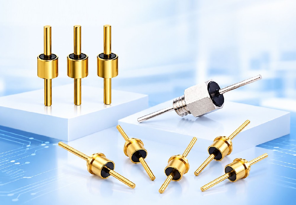
When a signal or power line passes through a shielded enclosure, the wall penetration decides how much EMI escapes. Feed-through filters are built for exactly this point: multilayer ceramic technology with a 360° grounding structure that keeps grounding impedance extremely low across the high-frequency range. They are widely used in electronic instruments, radio and communication facilities, signal and data lines, DC power lines, and military, aerospace and automotive electronics.
Why 360° grounding is the whole point
A surface-mount filter relies on small ground vias and pads; a feed-through filter's metal shell bonds to the panel or PCB around its full circumference. That 360° joint — soldered or clamped — is what delivers stable, predictable filtering at frequencies where conventional decoupling starts to leak.
Threaded filters: no soldering, easy service
Threaded packages (M2.5, M3, M4, M5, M6, M8) mount with a hex nut — compact, lightweight and removable. They suit panels that need periodic access or frequent reconfiguration. Both C and π circuits are available, with nickel/zinc-plated steel shells and resin sealing. Mounting torque reference: M2.5 = 0.15 N·m; M3–M5 = 0.4–0.6 N·m; M6 and above = 0.8–1.2 N·m.
Solder-in filters: compact C-type workhorses
Solder-in filters (HC2016, HC3630, HC4033) are smaller and lighter, with gold-plated shells that take a full 360° solder joint. They target high-density small-signal filtering, high-capacitance power lines and general-purpose panel penetrations. Pin diameters are Φ0.5 or Φ0.7 mm, with pin lengths of 14–16 mm.
C, LC or π: match the circuit to the noise
A single C-type feed-through capacitor is the baseline — compact and effective for general attenuation. LC adds an inductor for enhanced filtering where the noise spectrum is broader. π (two capacitors plus an inductor) delivers the deepest insertion loss for demanding power lines and high-noise environments.
Key specifications at a glance
| Parameter | Specification |
|---|---|
| Circuit types | C, LC, π |
| Packages | Threaded (resin-sealed) / solder-in (glass or resin) |
| Outer diameter | Φ2.0 – Φ8.0 mm |
| Rated voltage | 50 Vdc – 3,000 Vdc |
| Capacitance range | 0.5 pF – 10 µF |
| Dielectric | NPO: tgδ ≤ 0.0012 · X7R: tgδ ≤ 0.025 |
| Operating temperature | −55 °C to +125 °C |
| Withstand voltage | 2.5 × rated voltage, 5 s, no failure |
| Insulation resistance | ≥10⁵ MΩ at 25 °C |
| Typical rated current | up to 10 A (C-type reference model) |
A typical C-type reference model (LC3325N200V101M2808) measures 100 pF at 200 VDC with ≤0.12% dissipation factor, 10,000 MΩ insulation resistance at 100 VDC and a 10 A rated current — a useful benchmark when comparing quotations.
Installation practices that protect performance
Check panel cut-out dimensions before assembly; keep grounding surfaces clean and flat; torque threaded parts to specification rather than by feel. For solder-in types, solder the shell over the full 360° within 300 °C and about 3 seconds per joint, using a temperature-controlled iron or reflow. Never strike the body with hard objects, exceed 125 °C in continuous operation, or apply DC above the rating.
RFsatellite offers threaded and solder-in feed-through filters from standard part numbers through full customization. Share your line impedance, frequency band and panel geometry through our project inquiry form, and we will recommend C, LC or π options with insertion-loss expectations.